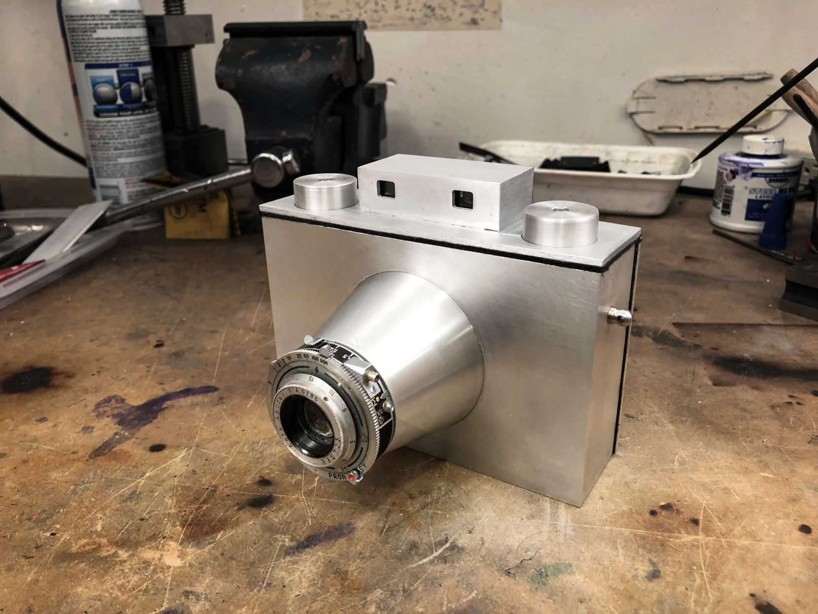
Landers AL6 Mark II
This is the most recent, and most advanced camera, I have made. The all aluminum construction makes this medium format camera light enough to take everywhere and strong enough to stand up to the most demanding situations.

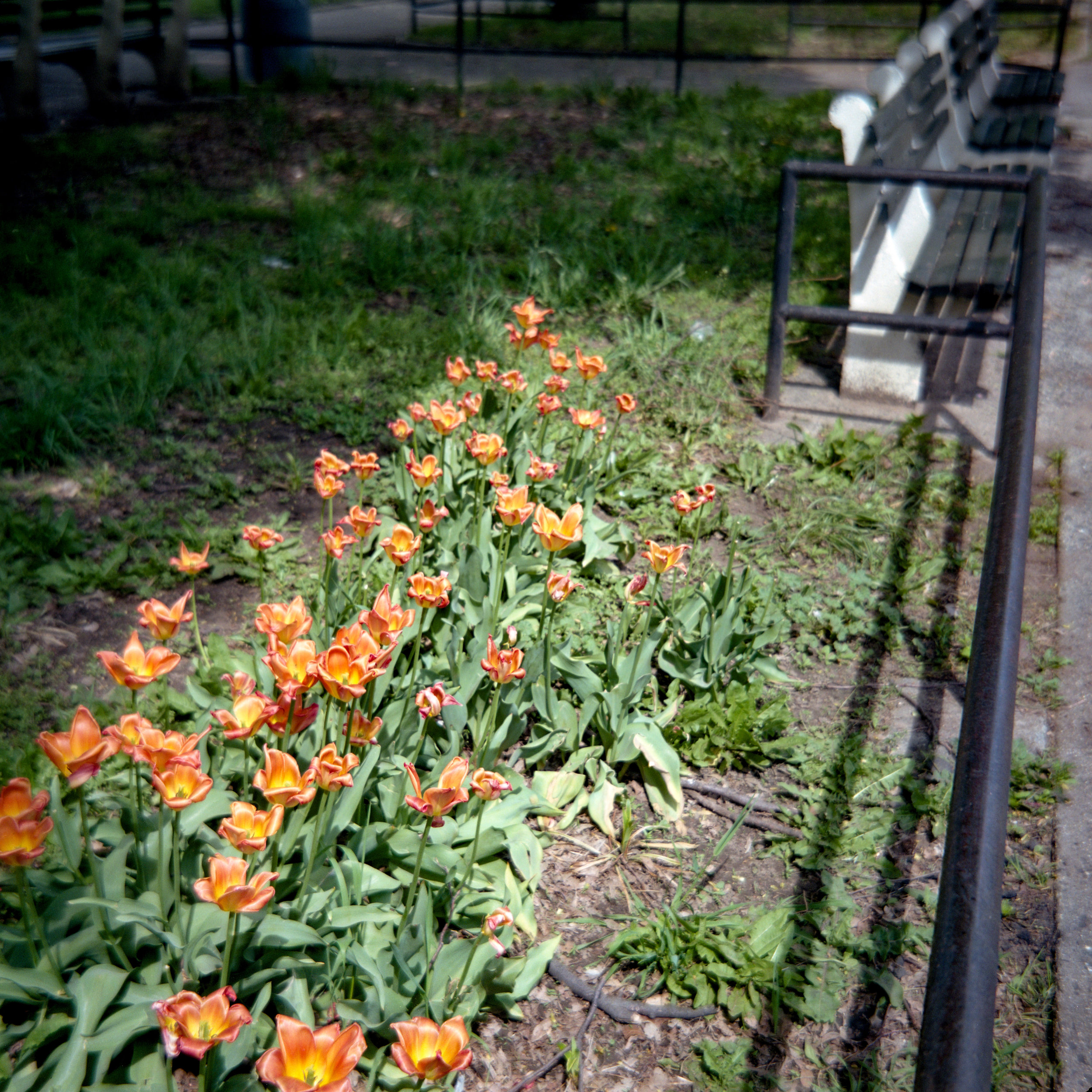
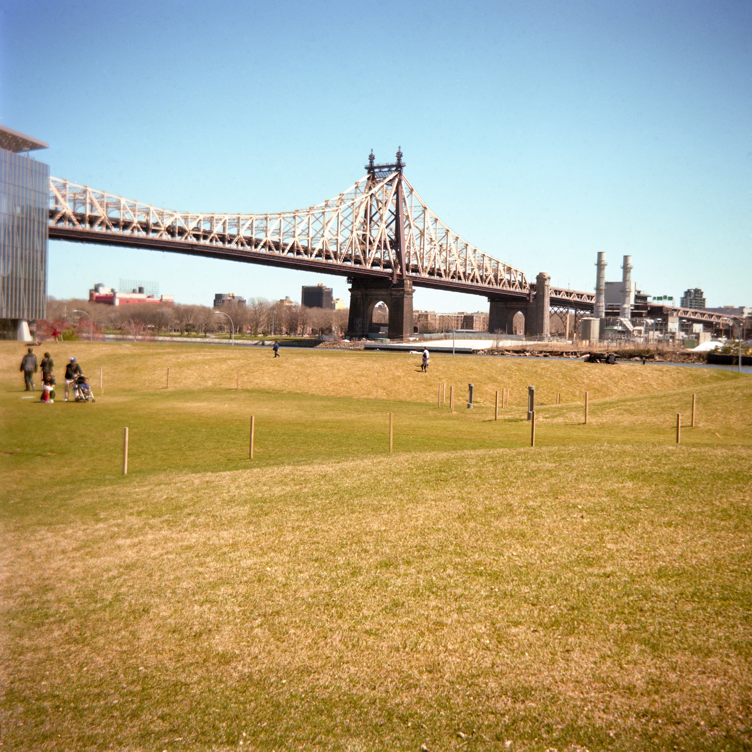
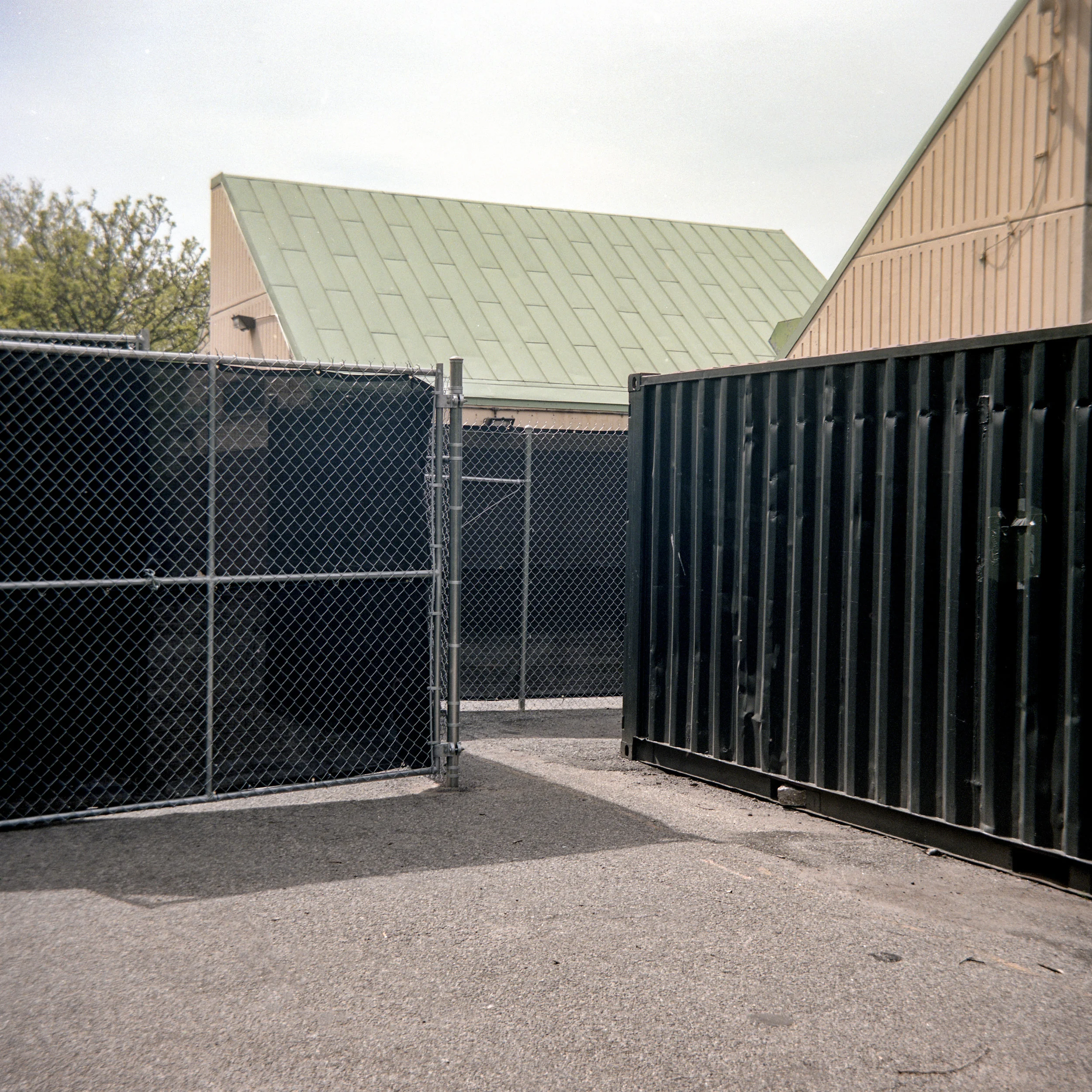
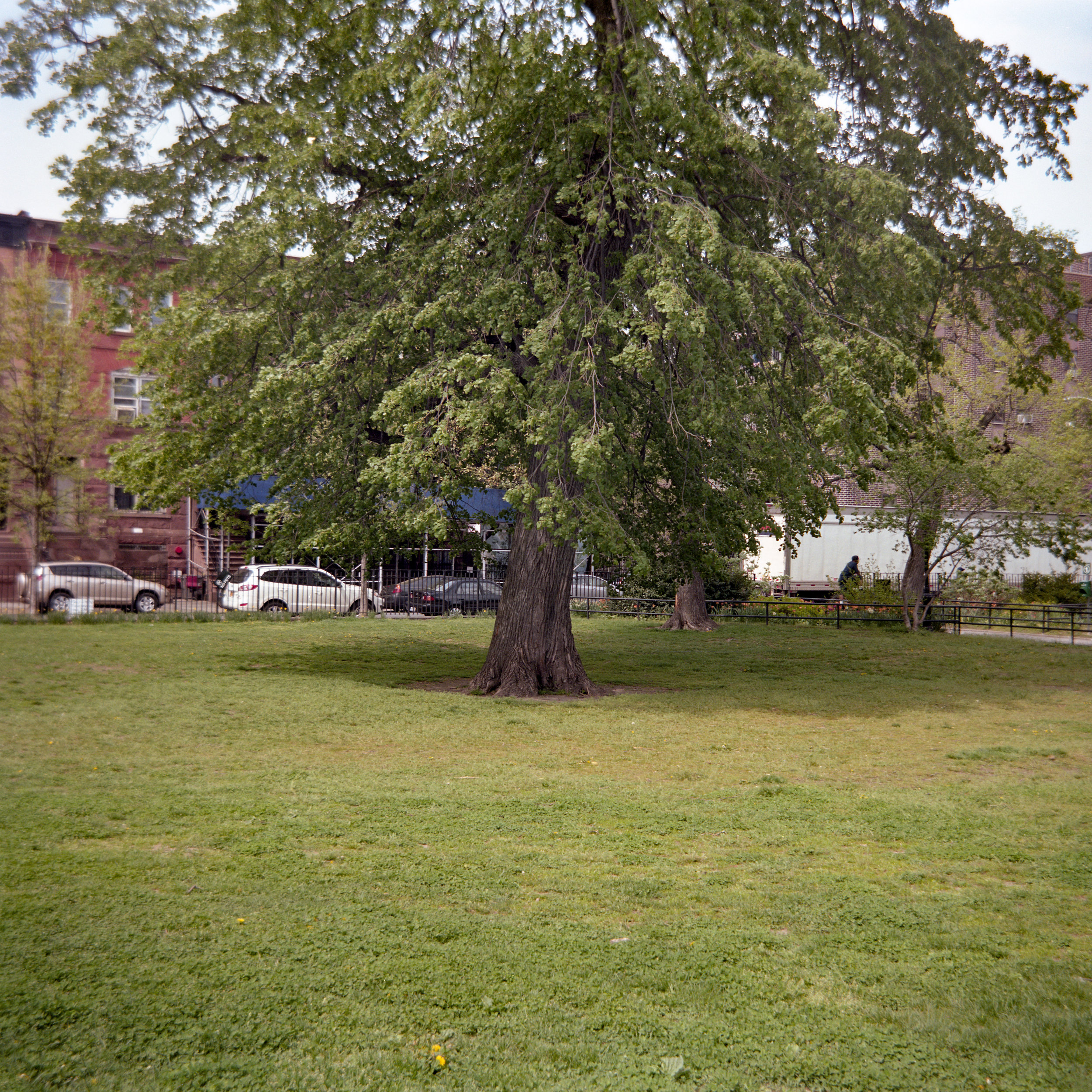
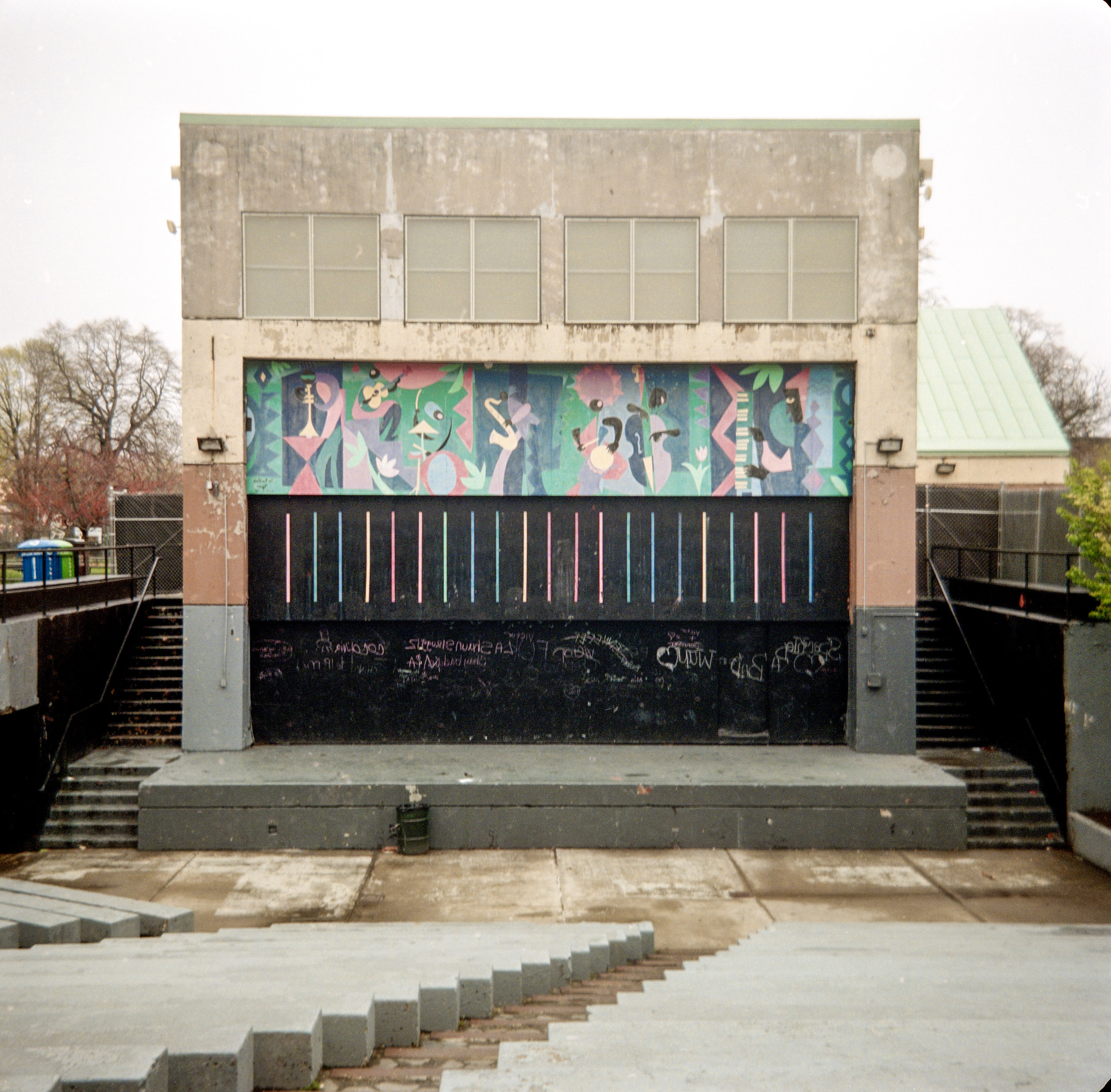
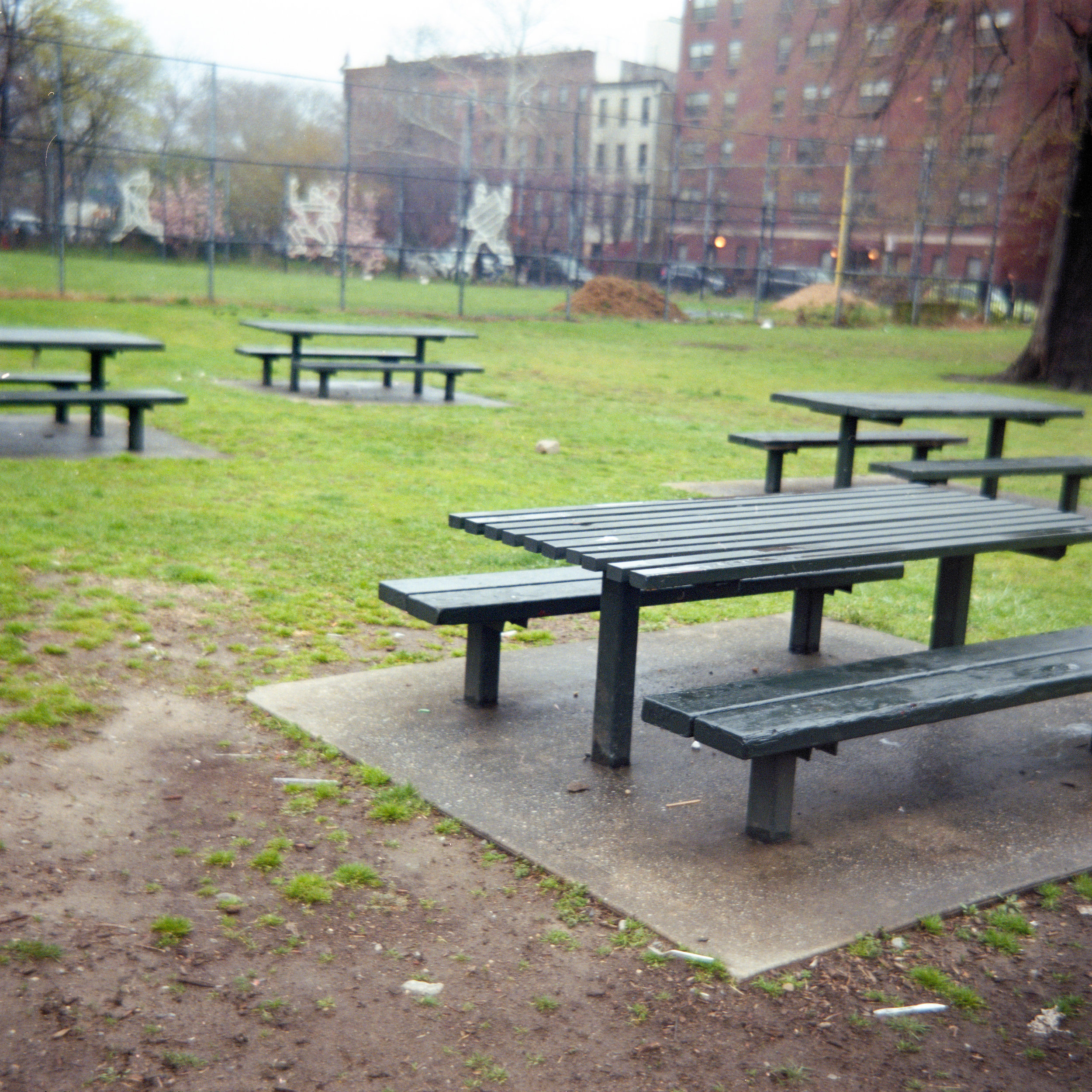
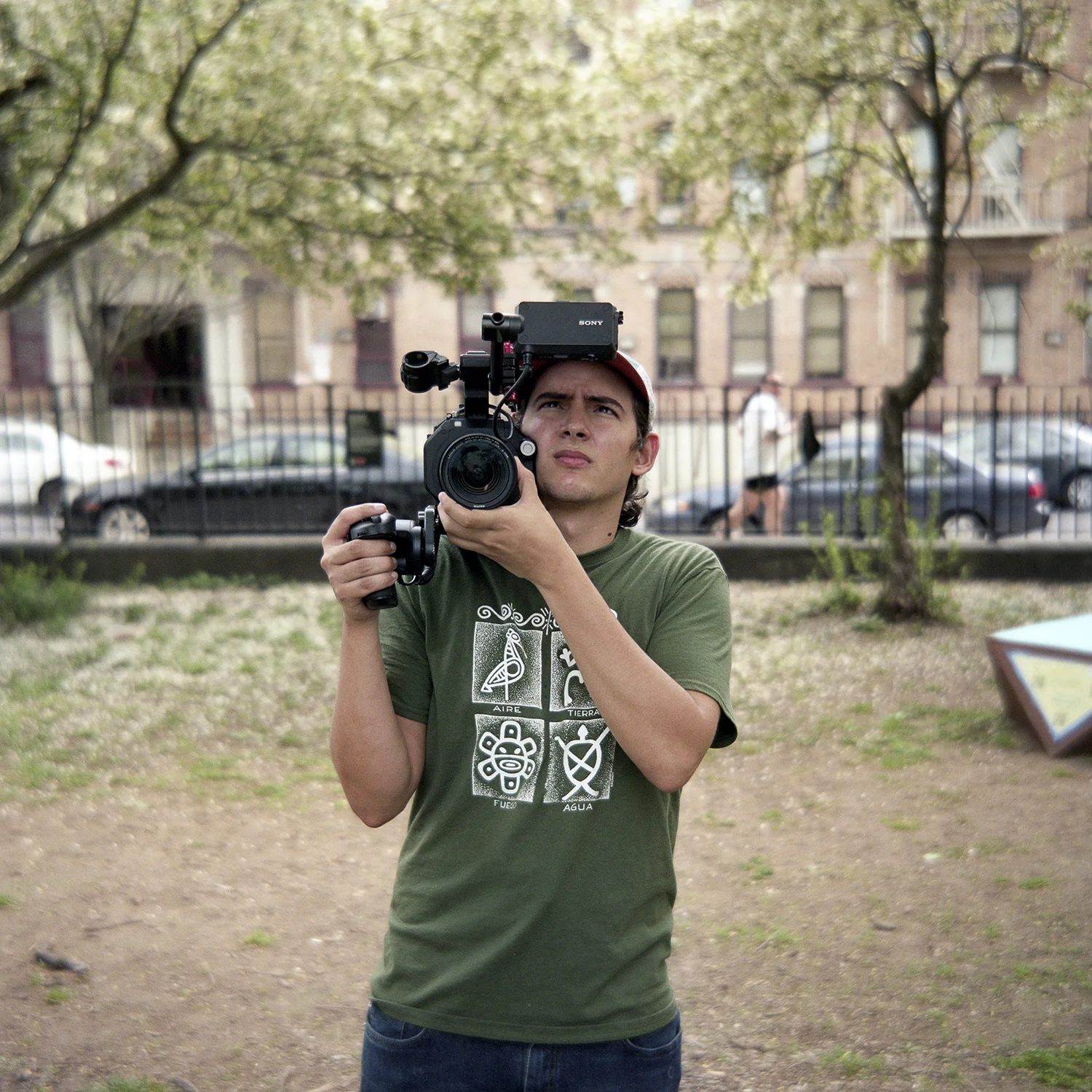
The Photos
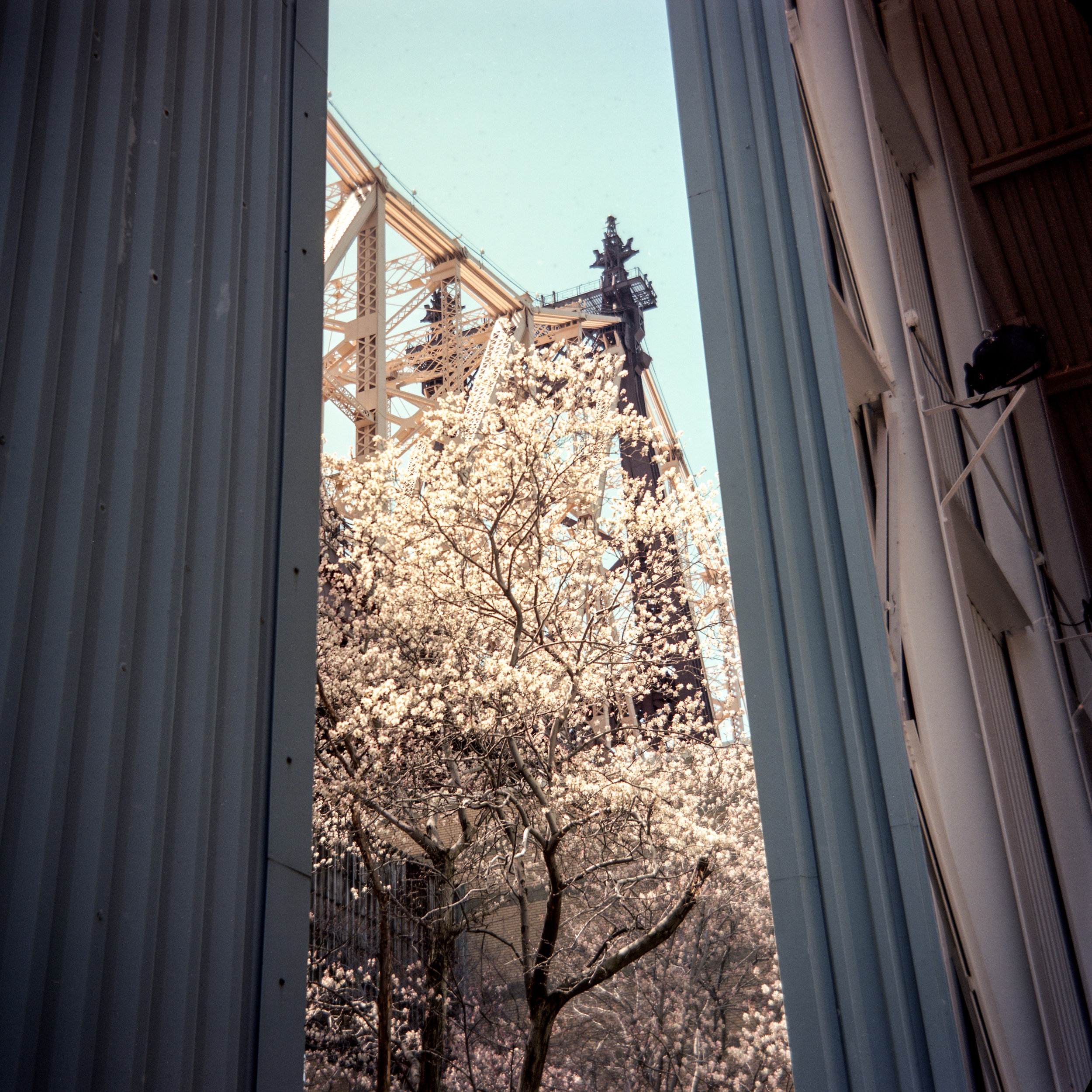
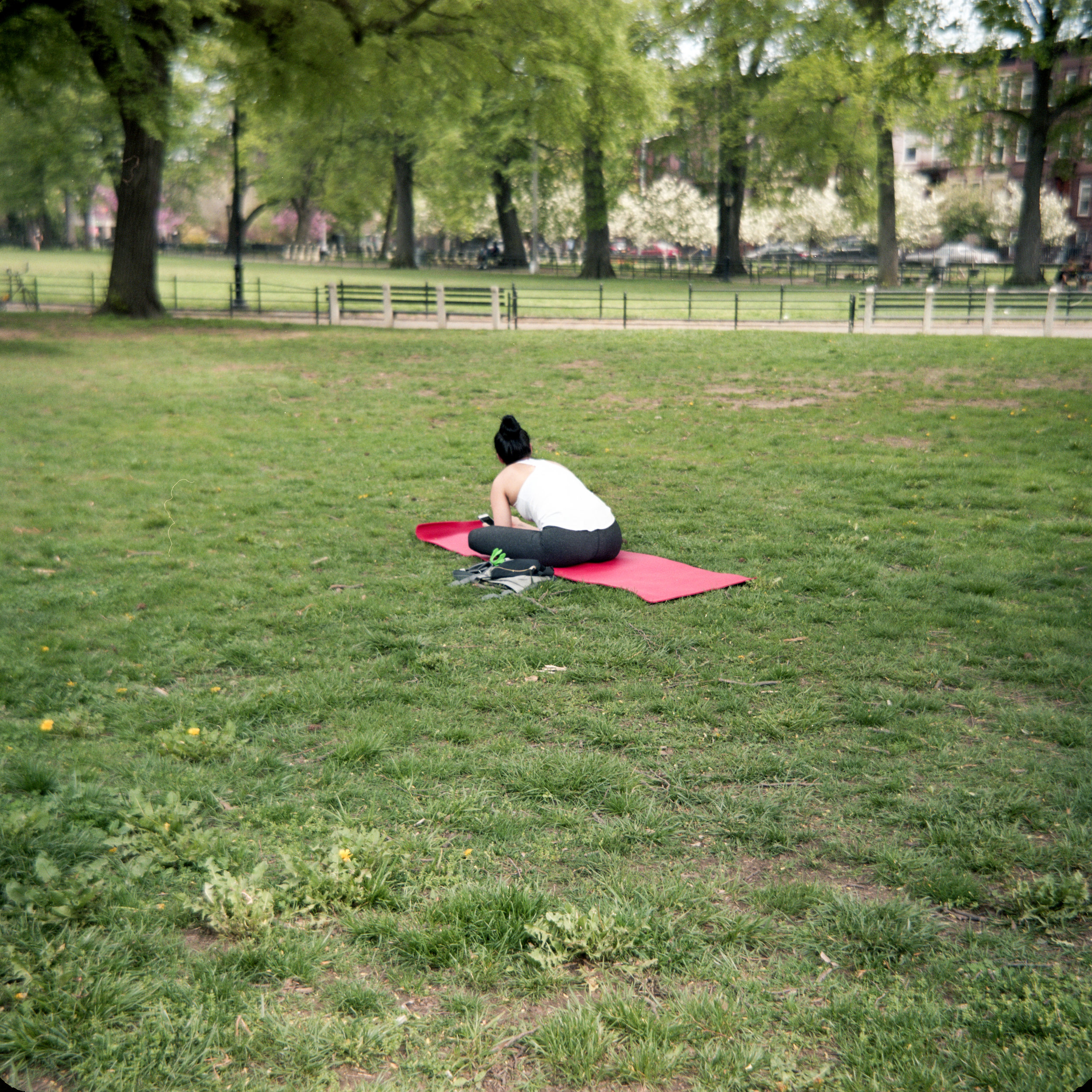
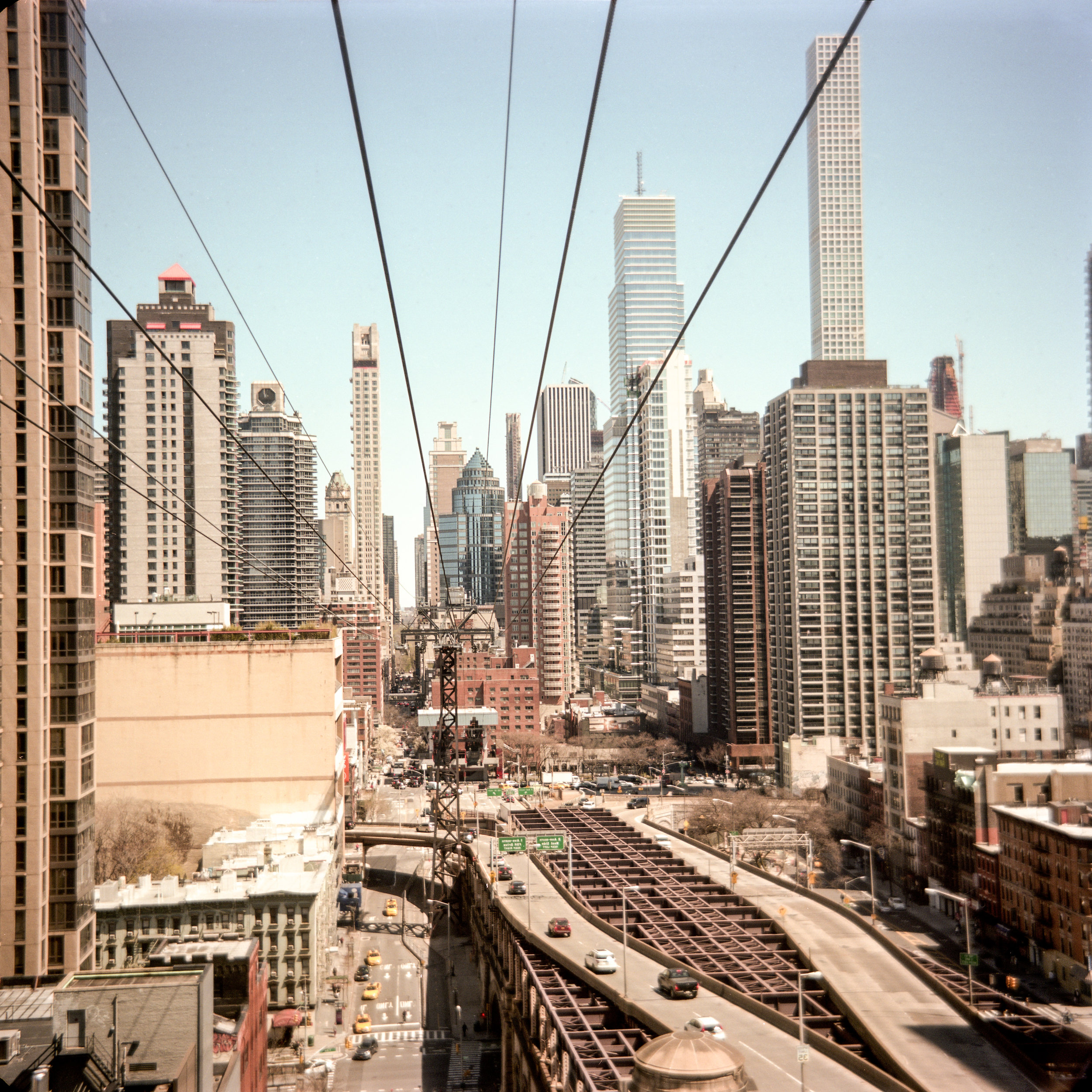
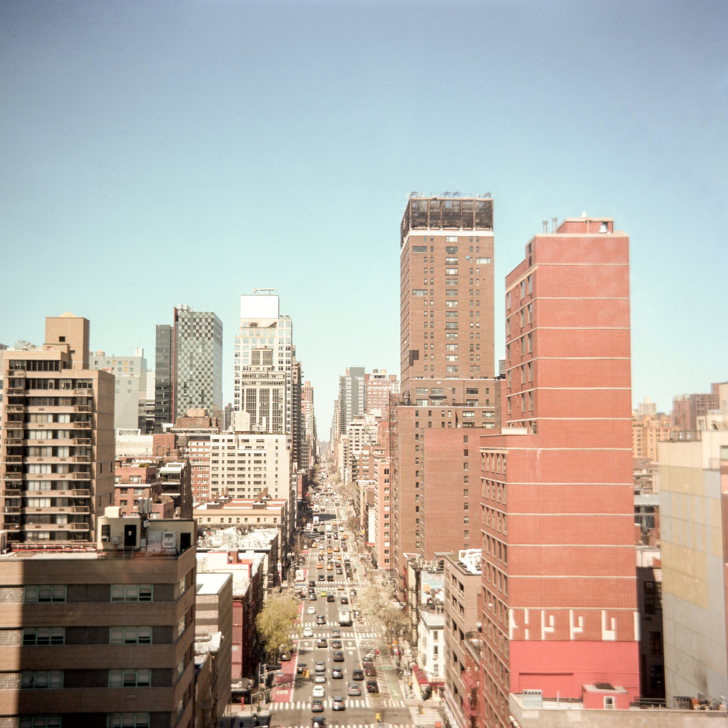
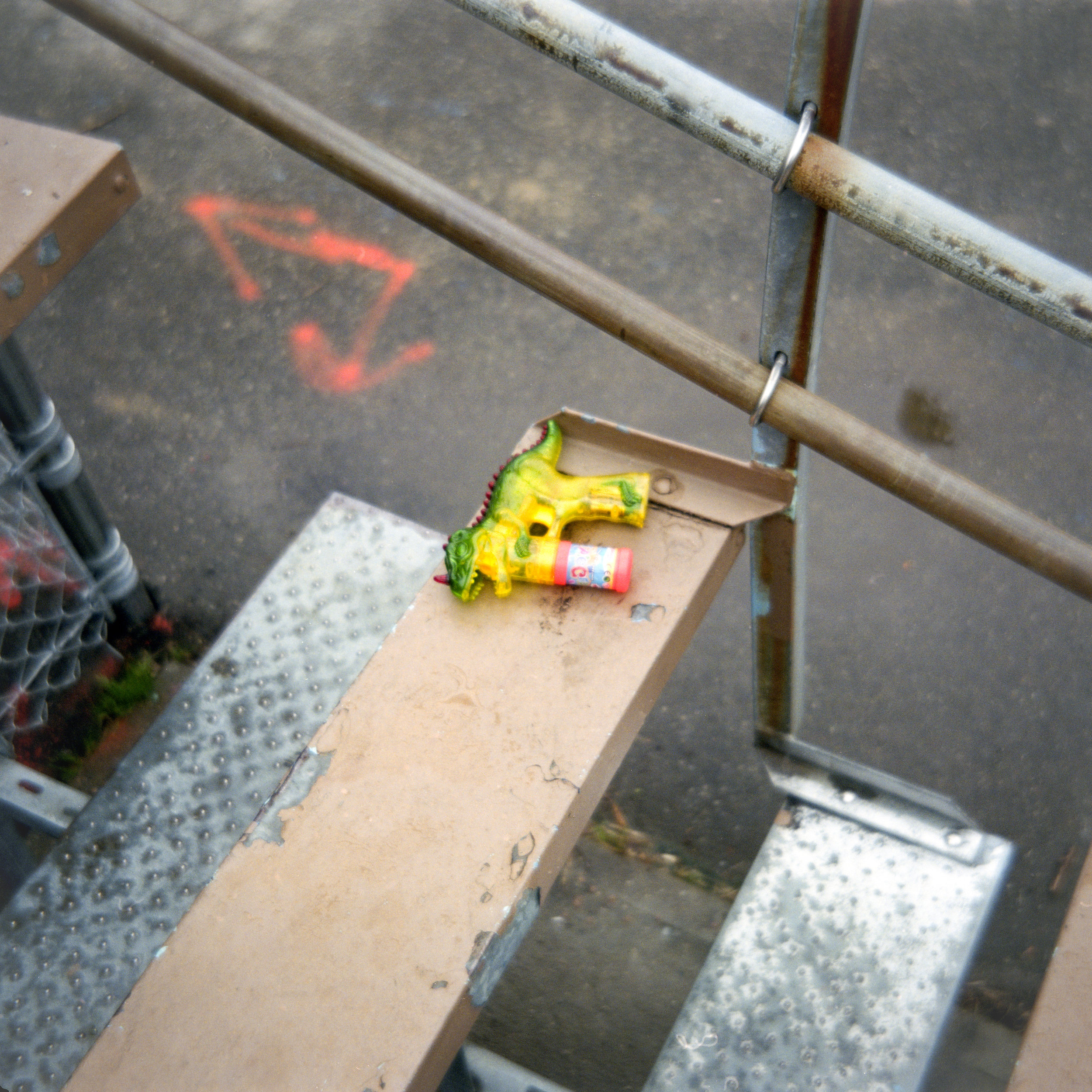
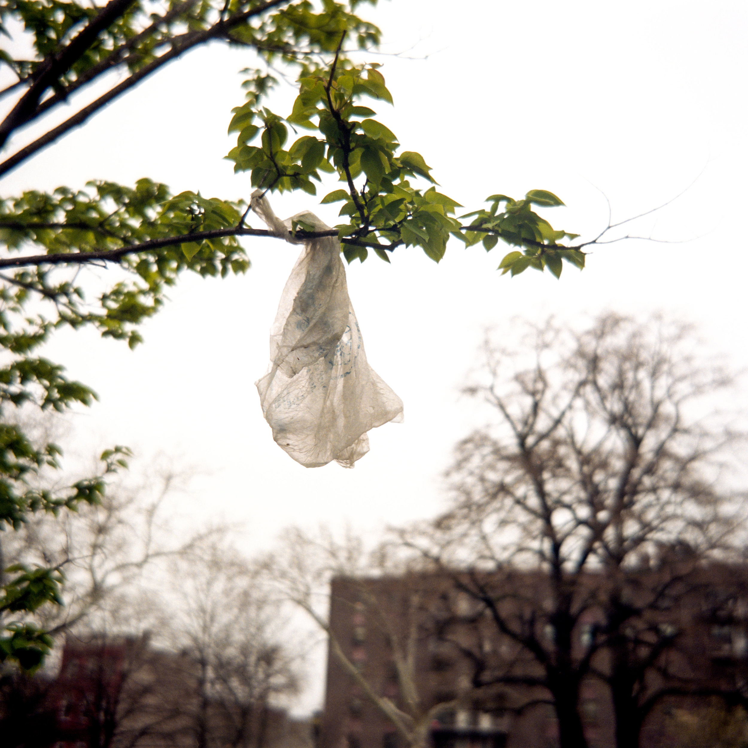
I have only shot a few rolls with this camera up to this point but the images are showing some real promise. The camera is very easy for me to use and the quality of the image are unique. A real joy to shoot with!


Check out the video where I discuss the image quality:
These images were scanned on an Epson V700 flat bed scanner using the standard film holders at 2400 DPI.
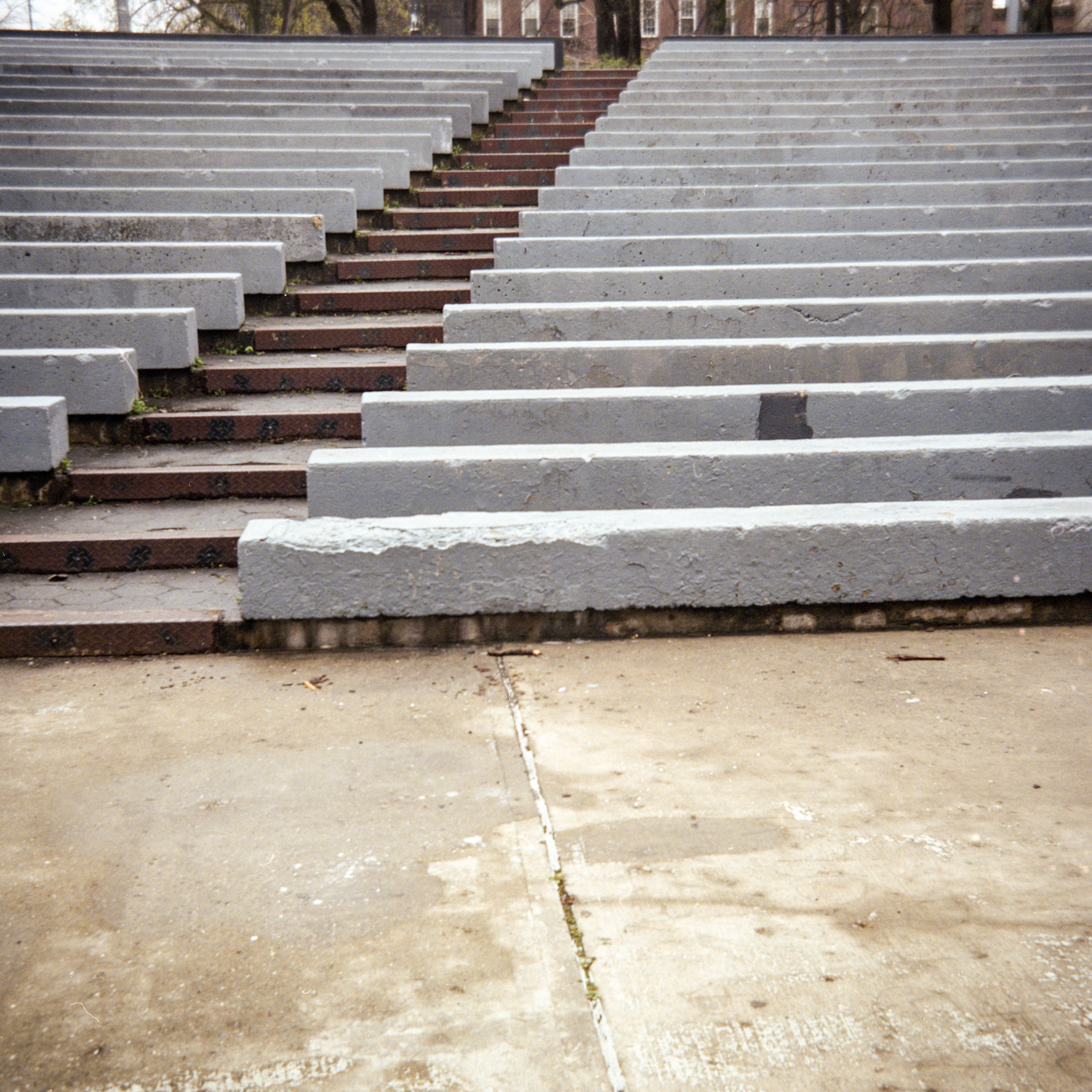
Here is a crop at 100%:

The photos are surprisingly sharp. Not Hasselblad sharp, but sharper than most basement made cameras.
The Build Process
I have created an in-depth video series documenting the build process of this camera.
The process involves several different fields of study including machining, casting, welding, and even 3d printing.
I have also created an abridged version here for you to enjoy!
Casting the Nose cone:
The first part I made was the nose cone.

This part is created with a combination of 3D printing, aluminum casting, and machining.
The new version of the nose cone is slightly larger and incorporating a steeper taper for aesthetic reason.
Here you can see the original and new design side by side.
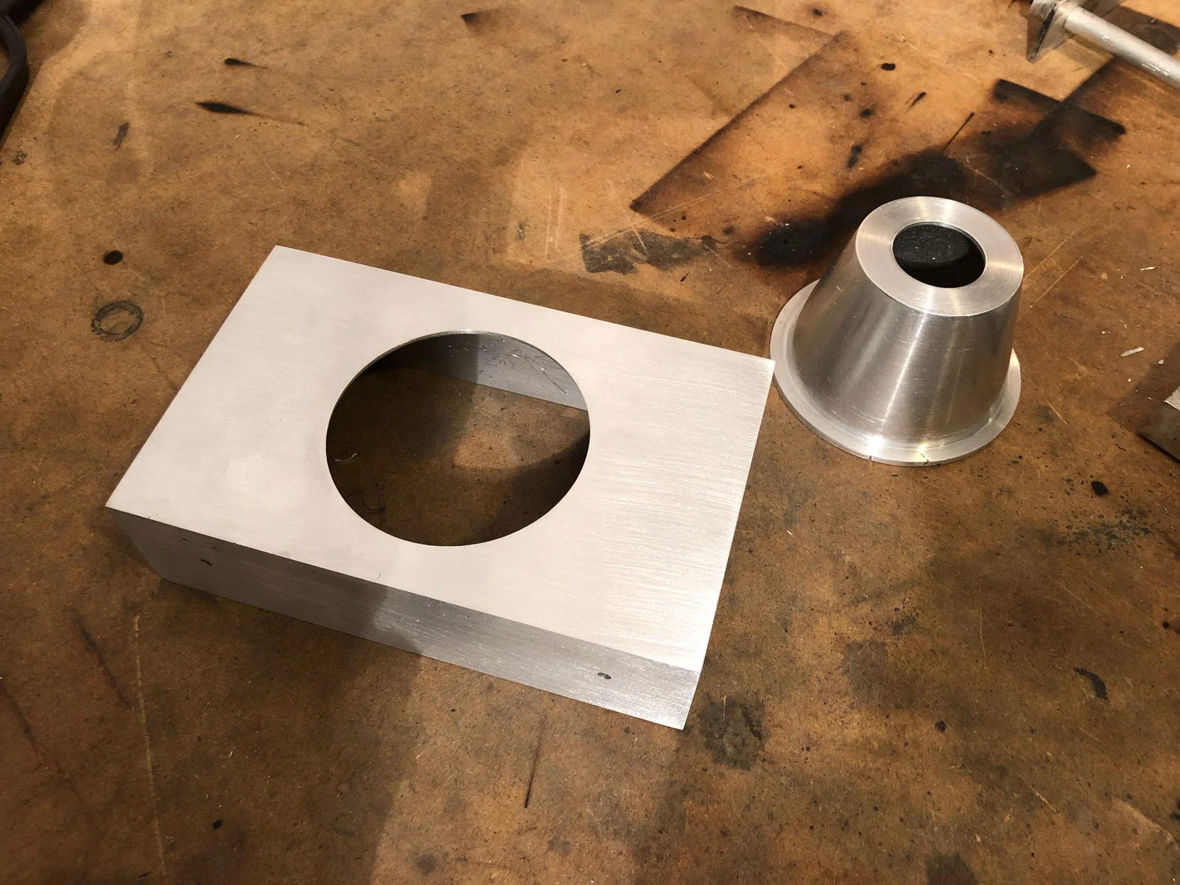
Welding the Main Body:
Next up is the main body.
In the previous version of this camera, this part was made using a single piece of aluminum that was bent into a box shape and then brazed together, but for this version I decided to learn how to weld and make it the right way.
The body is welded, machined square, and then a hole is cut in the middle using a rotary table.
It now comes time to join the main body and the nose cone. This is done using a press fit. The body is heated with a MAP gas torch while the cone is chilled in ice water. In a speedy fashion I bring the two together and clamp them. Once the temperature is equalized they are permanently bonded.
Click here to go to episode three of my video series where you can see this process in action.

Casting and Machining the Top Cap
The top cap is the last major body part to be made. The design is very simple and could easily be made out of bar stock, but to save time and money I decided to cast it.
During the process, I learned a lot about casting and repairing defects.
Check out episode 4 of my video series to see how I deal with these.

The Process starts with a 3d printed pattern. I don't include any of the features in the pattern as I find that its often easier to machined them in later.
The part is also made over sized so that it can be trimmed down to the exact size once its mounted to the body.

At a later point, I'll install this rangefinder into the top cap. While this rangefinder can be adjusted, I locked it to 6ft as I have found that when I use this camera I usually don't want to mess with adjusting a rangefinder.
This camera uses zone focusing, so you have no way of seeing through the lens if the image is in focus. With the rangefinder set to 6 ft, I set my lens to match and then move my whole body till the image in the rangefinder is in focus.
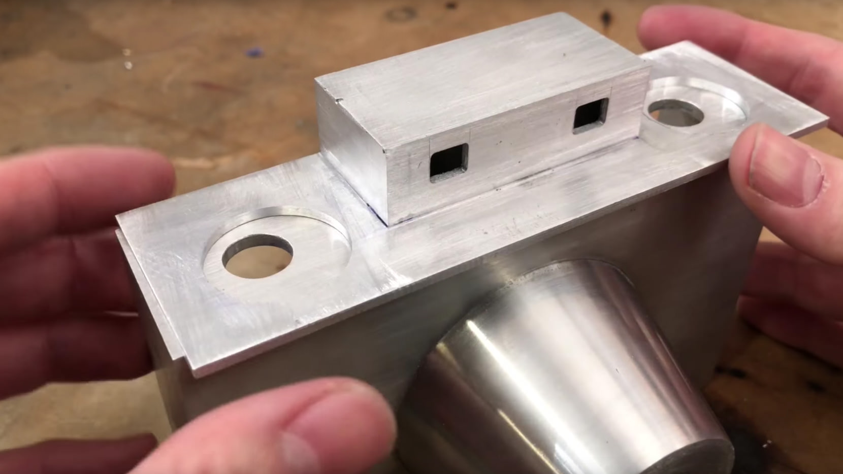
Building the Film Plane:
This is one of the more important parts in determining the quality of the camera. The flatter this plane is, and the better able the film is to lay flat against it, the better the quality of the image will be.

The part is welded together from flat stock. Then a surfacing cut is made over the from to make sure its perfectly flat.
I then grind the edges over so that they are perfectly smooth and rounded.

This part will not be attatched yet as I want to finish all other machining processees on the body before doing so.
When I do it is very important to get the film plane as perallel as possible to the lens mount on the nose cone.

Some of the Small Stuff:
It's at this point I start making some of the small stuff. These consist of the tripod mount, the camera strap mount, and some of the film advance hardware.

Here you can see my shop made super glue arbor being used to hold the piece of metal that will eventually become the tripod mount.
This arbor is used heavily in my machining process as it is a quick and efficient way of holding parts that would otherwise require complicated clamping arrangements.
The Back Door:
The back door itself is simply a piece of aluminum cut down to size. The interesting stuff comes with making the hinge.

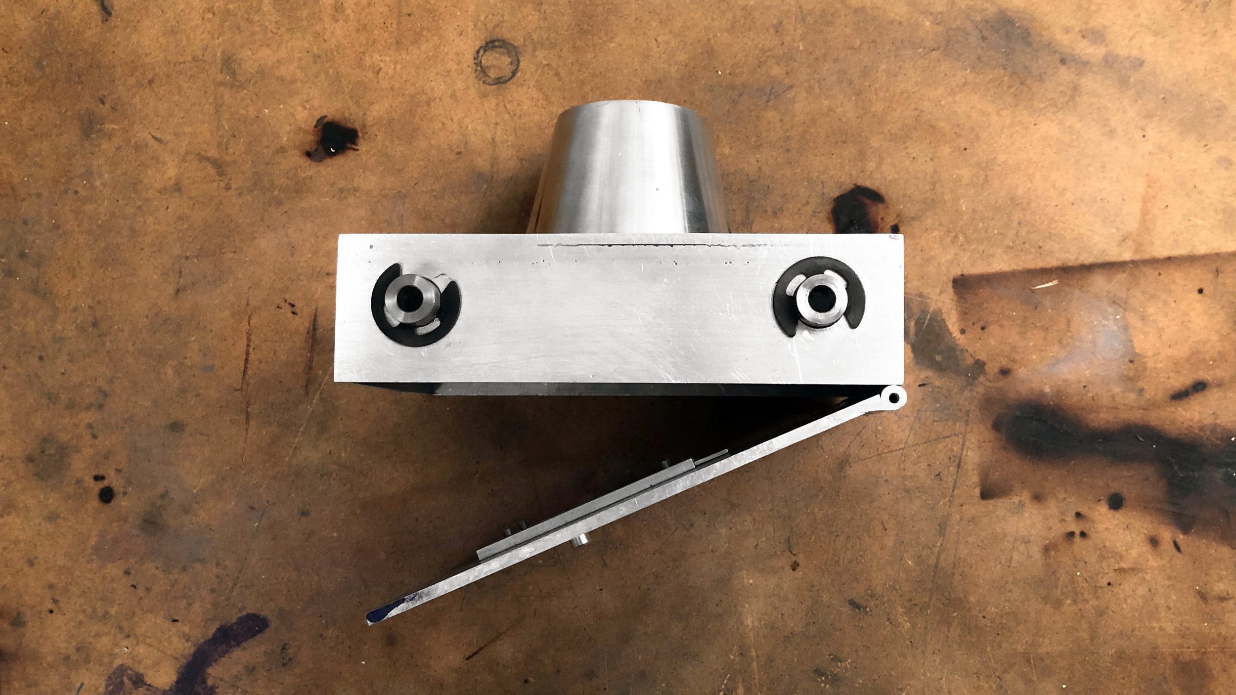
The hinge is cerated out of three sections of aluminum rod that I drill out. Two of the pieces are welded to the back door and one of them is welded to the main body.
When a rod is threaded through all the pieces the part now becomes a hinge. When the build is done the ends of the rod will be rivited to make it permenent.

The other part of this step of the build is the sliding window on the back door that will allow you to see the frame number.
This is a feature that is unique to cameras that use medium format film. The film itself is backed with paper, upon which frame numbers are printed for various formats. To advance from one frame to another I open this window and rotate the knobs on the top of the camera till the next number appears in the window.
Making the last Parts:
There are just a few last pieces to make, mostly the spring back to keep the pressure on the film, and the remainder of film advancement hardware.


This is the first time I have made my own pressure plate. In the past I had just dug them out of old cameras. But I wanted to give it a try.
The springs are made out of an old saw blade that are epoxied to a very flat sheet of brass. This should be enough to keep the film flat.

This is the spring loaded drive plate. The brass bar sits in the film spool and the knobs on top of the camera are rotated to advance the film.
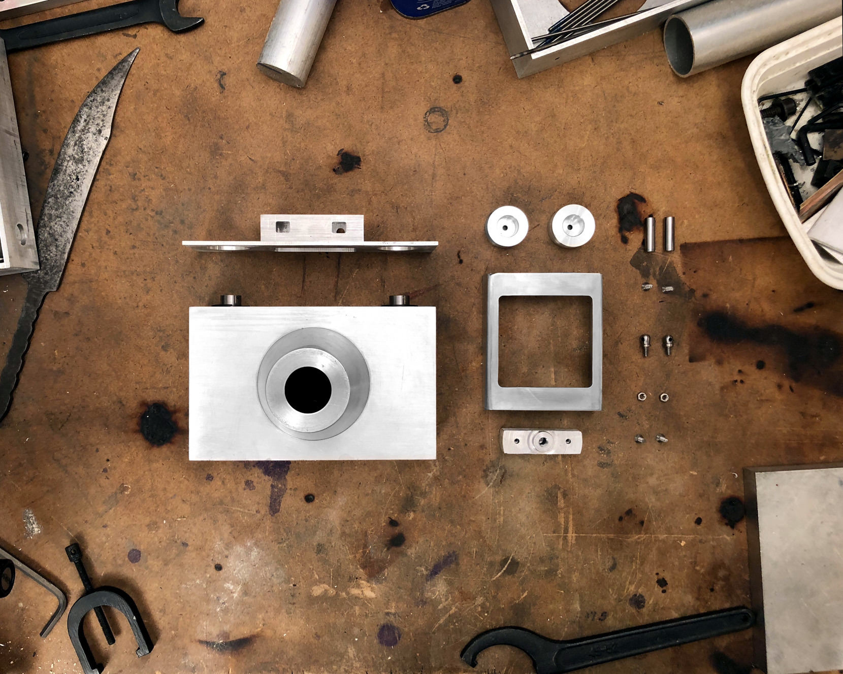
Assembling The Parts:
With everything now made, Its time to finish putting it all together.


To hold the back door closed, I simply use magnets, and it works really well!
Here you can see me attatchem them to the main body. To do so I 3D printed a jig that makes it very easy to align them, and then a few drops of super glue on each keep them where they belong forever.
The inside is then painted black and lined with felt.
The film plane isn't painted as I'm afraid the paint may have adverse effects on the film.
When it comes to lining the inside with felt I take my time as any gaps may cause light leaks.

The last of the hardware is added and this camera is now completed!